Disadvantagesof Auxiliary Relays
Single Busbar Configuration
Single Busbar with Bus section Configuration
Single Busbar with Transfer busbar configuration
Single Busbar with Bus section + Transfer bus coupler + Section Isolator configuration
Double Busbar with Bus coupler Configuration
Double Busbar with Bus coupler + Bypass Isolator Configuration
Double Busbar with Bus coupler + Transfer Buscoupler configuration
Mesh Busbar configuration
One and Half Breaker Busbar Configuration
More
An auxiliary relay is a supporting device used in substations. Unlike primary protective relays that detect faults, auxiliary relays assist them by providing additional switching, isolation, and logic functions.
Key Roles in Protection
Extra Contacts
Many protection relays have only a few contacts. Auxiliary relays expand this by offering several NO/NC outputs for tripping, signaling, and interlocks.
Highly Rated
Since protection relays are designed with low-power contacts, auxiliary relays handle the higher current needed to operate breaker trip coils and heavy control circuits.
Electrical Separation
They isolate delicate protection devices from high-energy breaker circuits, increasing system safety and reducing stress on the main relay.
Logic & Control
Used to build simple logic (AND/OR, seal-in) that ensures proper coordination between different parts of the protection system.
Trip Circuit Monitoring
Some auxiliary relays supervise the trip circuit and raise an alarm if there’s a fault, ensuring reliable breaker operation.
Lockout (Master Trip Function)
In critical cases, an auxiliary relay is used as a lockout (ANSI 86), preventing equipment from being re-energized after a severe fault until manually reset.
CT switching and VT changeover
Auxiliary relays play an important role in CT switching and VT changeover by ensuring safe operation and proper sequencing. They prevent CTs from being open-circuited, control VT selection between relays or meters, and provide interlocking and status indication. This makes the switching process reliable, safe, and efficient.
Applications in Substations
Initiating trips for multiple breakers from one protective relay.
Holding (seal-in) trip signals until an operator acknowledges them.
Providing alarm outputs for operators.
Supervising breaker trip circuits for health and reliability.
Acting as an interlocking element in busbar and transformer protection.
Switching Circuits in CT / VT
Disadvantages
01.Delay in tripping operation
One of the main disadvantages of using auxiliary relays in protection systems is the delay in tripping operation. When a fault occurs, the protective relay generates a trip signal, but if an auxiliary relay is connected in the tripping path, the signal must first energize the auxiliary relay before reaching the circuit breaker trip coil. This introduces an additional mechanical operating time, which slightly slows down the overall fault-clearing process. Although the delay is usually only a few milliseconds and may not affect performance in most cases, it becomes critical in high-speed protection schemes such as busbar or transformer differential protection, where every millisecond counts.
In the first one, the tripping delay that occurs when a protection system operates is caused by the combination of the IED trip and the circuit breaker (CB) trip. First, the Intelligent Electronic Device (IED) detects a fault and sends a trip signal. Then, the circuit breaker receives this signal and physically opens its contacts to interrupt the current. The total time taken by these two actions is very short, typically less than 30 milliseconds. Although it is not instantaneous, this delay is extremely brief and almost imperceptible, ensuring fast and reliable fault clearance.
In the second one, The tripping delay in this case is slightly longer because it involves three steps: the IED trip, the auxiliary relay trip, and the circuit breaker trip. First, the Intelligent Electronic Device (IED) detects a fault and sends a trip signal. The signal then passes through the auxiliary relay, which processes it before forwarding it to the circuit breaker. Finally, the circuit breaker receives the signal and opens its contacts to interrupt the current. The total time for these steps, including IED Trip, Aux Trip, and CB Trip, is usually greater than 30 milliseconds. Although still very fast, the extra step through the auxiliary relay introduces a small additional delay compared to a direct IED to CB trip.
The usage of auxiliary relays depends on specific standards and customer requirements, and it may vary some customers will use them, while others will not.
02.Power consumption
Using an auxiliary relay in a system increases overall power consumption because the relay’s coil requires energy to stay activated. Even though the power used by a single relay is small, it adds to the total load, particularly in systems with multiple relays or devices that need to operate for extended periods. This extra power requirement can cause the battery to drain faster, potentially necessitating a larger or higher-capacity battery to maintain the same operating time. To reduce this effect, low-power or solid-state relays can be employed, and the relay can be activated only when needed, minimizing unnecessary energy usage. Including an auxiliary relay can therefore have a direct impact on battery sizing in a design.
The power consumption depends on the size of the system, which in turn is determined by the trip coil’s power consumption and the number of auxiliary relays in operation. Refer the 03.Representaiton for increased battery size & Room size.
05.Charger Size / Charger Cabinet
When auxiliary relays consume more current, the overall DC load on the battery rises. To sustain the required backup period, the battery must have a higher ampere-hour rating, which can be achieved through larger cells or by adding parallel strings. As the battery capacity grows, the charging current demand also increases, requiring a charger with a higher output rating. The increase in charger output means that the connecting cables between the charger, the battery, and the DC system must be sized up to handle the additional current safely while avoiding overheating. In some cases, the larger battery bank also results in longer cable runs, which calls for even thicker cables to minimize voltage drop. This way, an increase in auxiliary load eventually leads to the need for larger charger cable sizes.
06. Cable Size
When auxiliary relays increase the continuous DC load, higher current must flow through the cables connecting the battery to the charger and from the charger to the LVDC board. To handle the increased current without excessive voltage drop or overheating, larger cross-section cables are required. This results in thicker and more expensive conductors, as well as more complex installation due to increased bending radius and cable management needs. Consequently, both material and installation costs rise in proportion to the upgraded cable size.
03.Changes in Battery Size
When auxiliary relays consume additional power, the continuous DC load on the battery increases. To maintain the required autonomy period, the ampere-hour capacity must be increased, often requiring larger cells or additional parallel strings. As the number or size of cells grows, the battery bank occupies more space, and both the equipment and installation costs rise accordingly
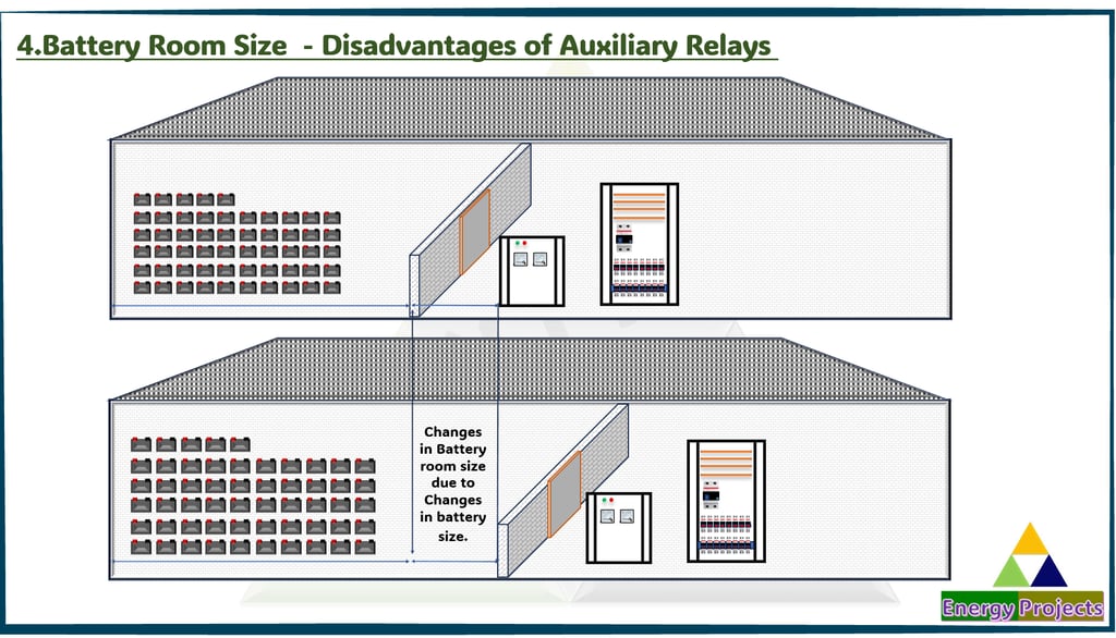
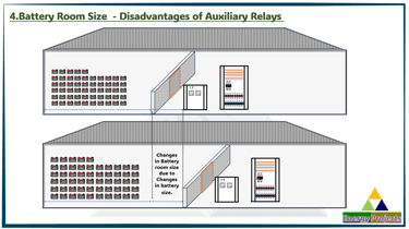
04.Battery Room Size
As battery capacity increases to support the additional DC load, the physical footprint of the battery bank expands. This enlargement requires a bigger battery room to safely accommodate the cells and provide adequate ventilation. The need for additional floor space, structural reinforcement, and safety systems results in higher civil and engineering costs.
07. LVDC Incomer MCCB Size
As auxiliary relays increase the continuous DC load, the current demand on the LVDC system rises. To safely protect the higher load, the incomer MCCB must be rated for a larger current capacity. This upgrade not only increases the physical size of the MCCB but may also require additional panel space and busbar sizing adjustments. The higher rating directly raises equipment cost and can also add to engineering and installation expenses.
08. LVDC Busbar Size / LVDC Cabinet
As auxiliary relays increase the continuous DC load, the current demand on the LVDC system rises. To safely protect the higher load, the incomer MCCB must be rated for a larger current capacity. This upgrade not only increases the physical size of the MCCB but may also require additional panel space and busbar sizing adjustments. The higher rating directly raises equipment cost and can also add to engineering and installation expenses.

09.Dependency
IEDs (Intelligent Electronic Devices) often rely on auxiliary relays to provide signal isolation, contact multiplication, or interface with higher-power circuits. In such cases, the correct operation of the IED is dependent on the reliable performance of the auxiliary relay. Any failure, delay, or malfunction in the auxiliary relay can directly impact the IED’s protection, control, or signaling functions, reducing overall system reliability.
10.Reliability
The reliability of the LVDC system decreases when auxiliary relays are introduced, as they add mechanical components prone to coil failure or contact wear, bounce, and sticking. Since IEDs may depend on these relays for signaling or tripping, a failure of the auxiliary relay itself or its contacts can compromise protection and control functions. This raises the risk of misoperations, delayed responses, and increased maintenance, thereby reducing overall system dependability.

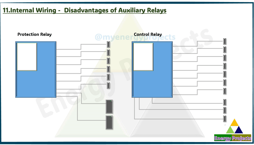
11.Internal Wiring
When auxiliary relays are added, additional internal wiring is required between the IED and the relay. This extra wiring increases the overall weight of the panel and may also demand a larger panel size to accommodate the wiring routes, terminations, and cable management. Moreover, the added complexity raises the installation and testing man-hours, further increasing overall project costs.

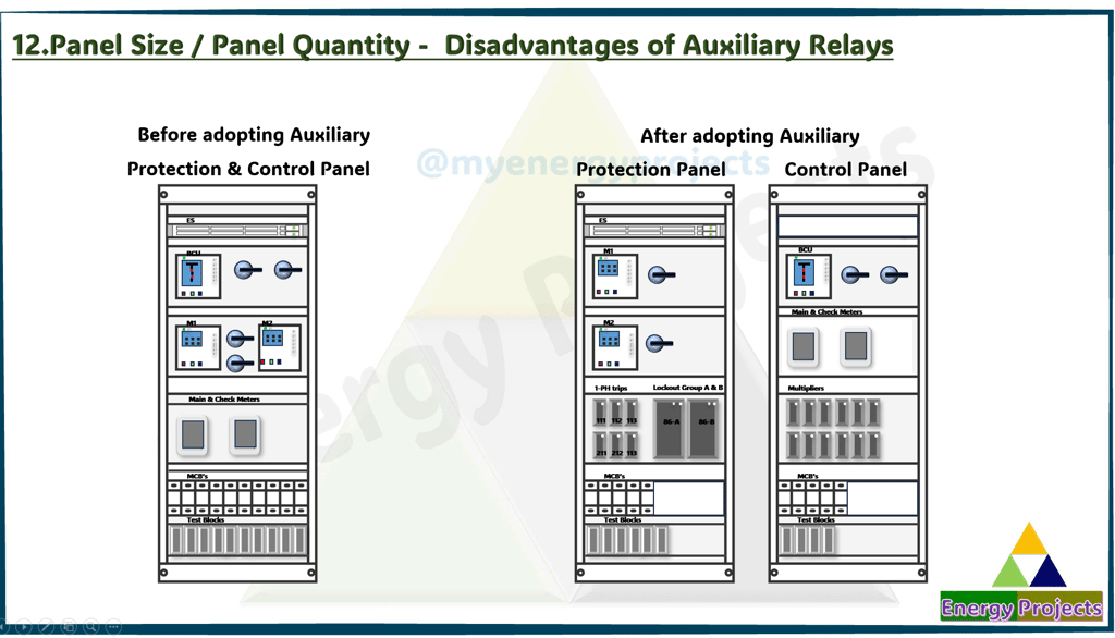
12.Panel Size / Panel Quantity
Introducing auxiliary relays increases the number of components, wiring, and terminations inside the panel. This often requires a larger panel to accommodate the additional relays, wiring ducts, and mounting arrangements. In cases where space in a single panel becomes insufficient, additional panels may be needed. Both scenarios result in higher material costs, increased panel weight, greater floor space requirements, and more engineering and installation man-hours.
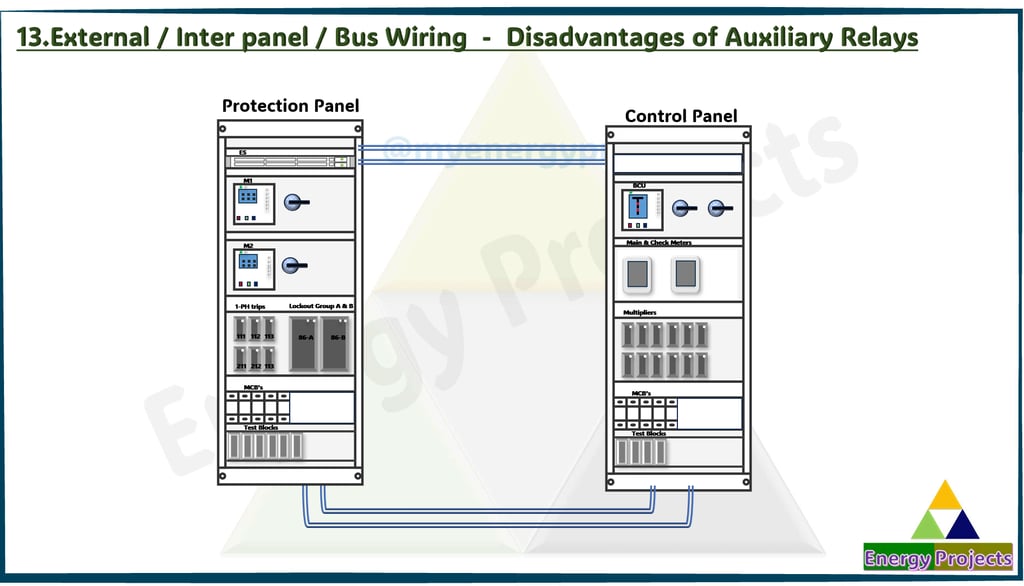
13.External / Inter panel / Bus Wiring
When separate control and relay panels are required due to the use of auxiliary relays, the amount of external wiring between panels increases significantly. This leads to longer cable runs, more termination points, and added routing complexity. Consequently, installation weight grows, additional space for cable trays or ducts is needed, and man-hours for laying, connecting, and testing also rise. These factors together increase material and labor costs while extending overall commissioning time.

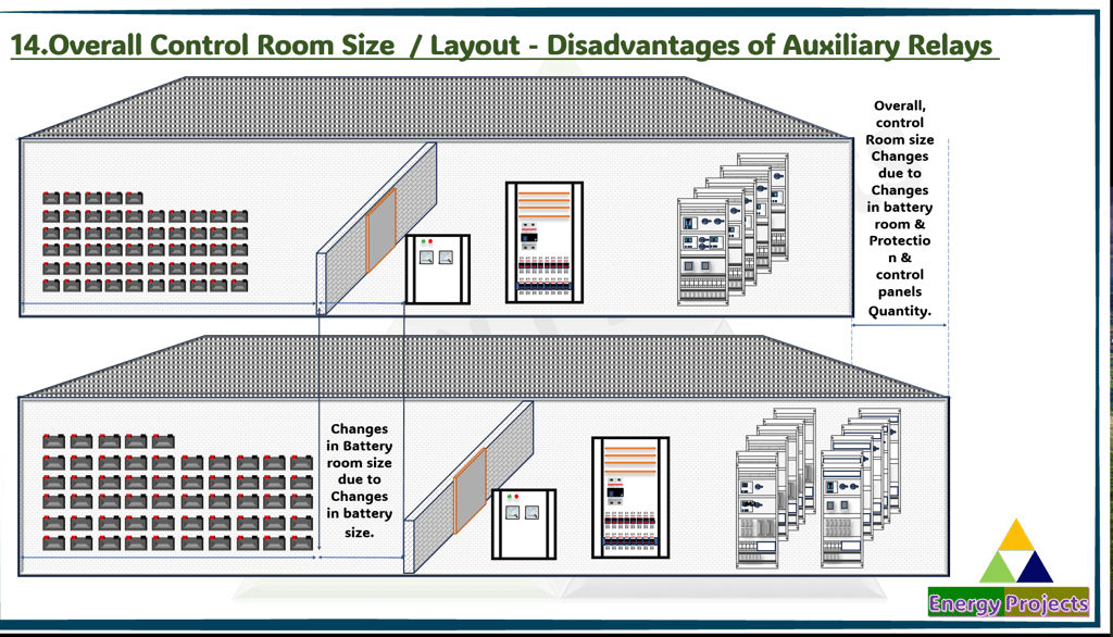
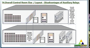
14.Overall Control Room Size / Layout
Overall Control Room Size / Layout - due to battery size and the increased number of panels resulting from the use of auxiliary relays, when separate control and relay panels are required, the amount of external wiring between panels increases significantly. This leads to longer cable runs, more termination points, and added routing complexity. Consequently, installation weight increases, additional space for cable trays or ducts is needed, and man-hours for laying, connecting, and testing also rise. Together, these factors increase material and labor costs while extending overall commissioning time.
15.FAT / SAT Duration
The FAT/SAT duration is expected to increase due to changes in the number of panels and the rise in auxiliary relay quantities. Additional panels require more wiring, testing, and verification, which extends the overall testing time. Similarly, the inclusion of extra auxiliary relays demands additional functional checks and coordination tests to ensure system reliability. These factors collectively add complexity to the procedure, requiring more resources and time. As a result, the overall FAT/SAT schedule will need to be adjusted accordingly.