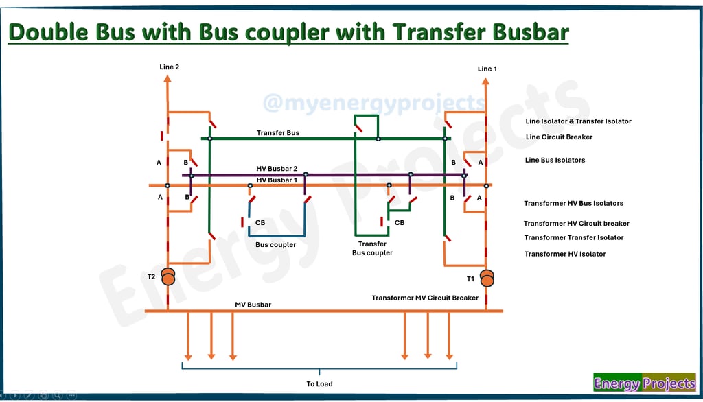
Double Busbar with Bus coupler with Transfer Busbar configuration
This configuration consists of Busbar 1 and Busbar 2 connected by a bus coupler, along with a third transfer busbar that serves the same function as the previously discussed bypass isolator arrangement. This setup offers increased operational flexibility, enables maintenance of breakers or busbars without interrupting supply, and enhances system reliability by allowing seamless load transfer between buses.
Load Transfer Condition with Transfer Bus Coupler during a Breaker Fault
To perform this operation, we need to ensure that all transfer isolators are in the open condition.
First, close the Transfer Isolator of the Transfer Bus Coupler and the Bus Isolator corresponding to the busbar to which the connection is to be made. Then, open the breaker associated with the Line 2 disconnectors.
Next, close the Transfer Isolator of Line 2, followed by closing the Transfer Bus Coupler Circuit Breaker to connect the line to Busbar 1.
You can now observe the power flow through the circuit.
The same method is to be followed if there is a problem with any other bay circuit breaker. However, note that only one bay at a time can be operated in this manner with the given busbar arrangement.