Double Busbar with Bus coupler Configuration
Double Busbar with Bus coupler
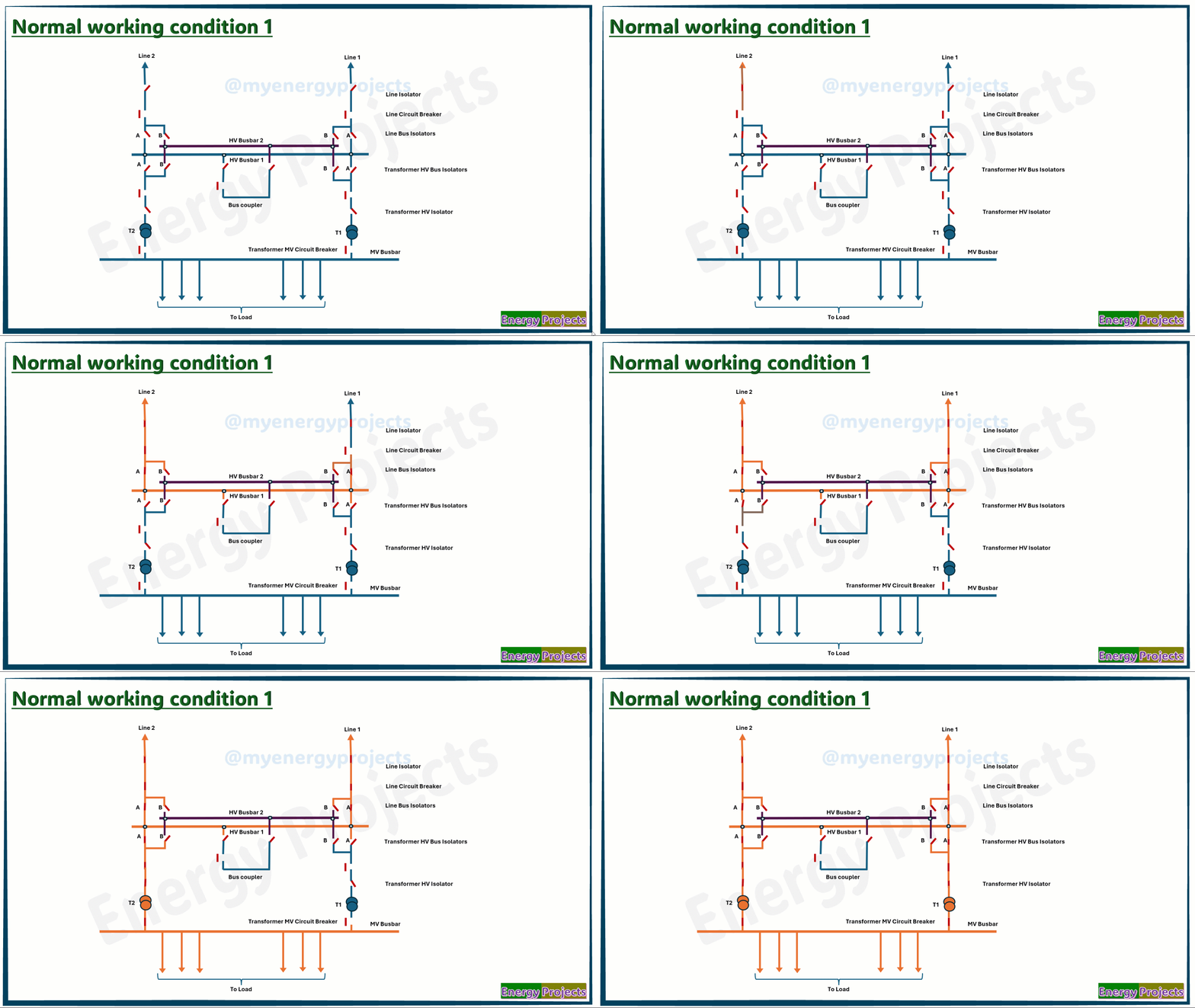
First, we look at the very simple representation of this busbar configuration, You can see Busbar 1 and Busbar 2 with a coupler. This is a common arrangement that is widely used.
Operation 1
In this case, all bays are connected to Bus-1, as shown in the operation and power flow diagram. Line 1 and Line 2 are energized, and Transformer 1 and Transformer 2 are also getting charged
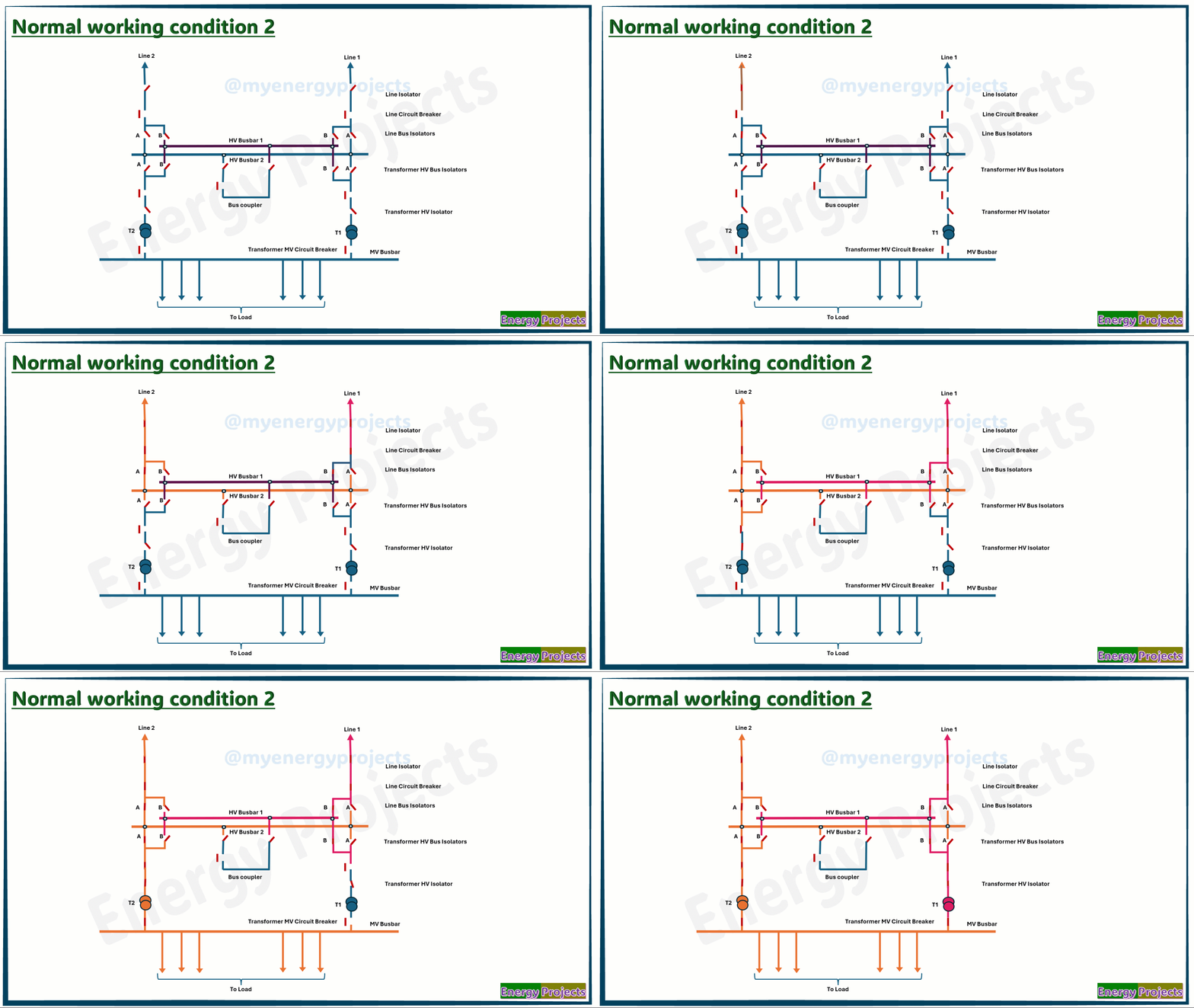
Operation 2
In this case, Line 2 is connected to Busbar 2, and Line 1 is connected to Busbar 1. Transformer 2 is associated with Busbar 2, while Transformer 1 is connected to Busbar 1. You can refer to the power flow diagram for a visual representation
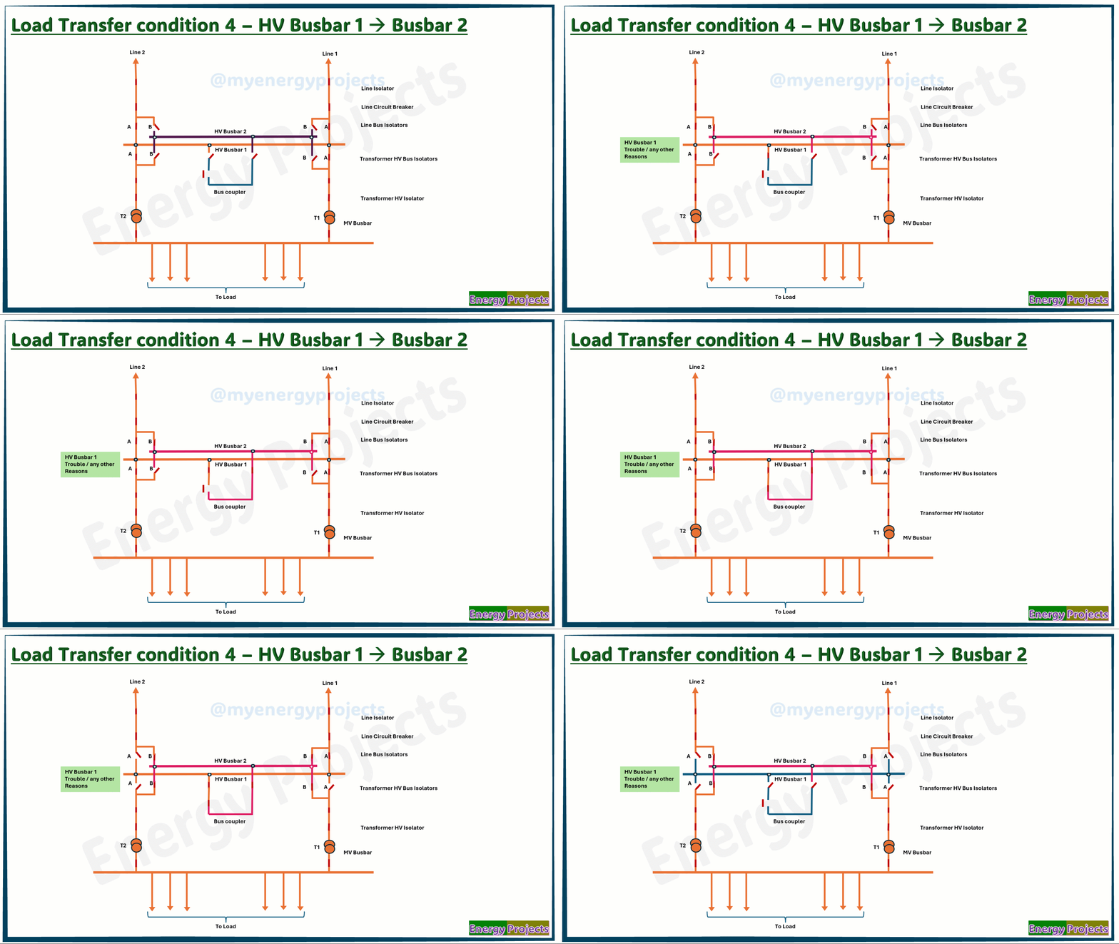
Load transfer condition - with bus coupler
Under load conditions, it is not safe to directly switch circuits from Bus-1 to Bus-2 or vice versa. This is because when attempting to operate the isolator, a potential difference between the two buses may exist. This can result in arc formation, which may damage the equipment.
To prevent this, a bus coupler breaker is used to ensure a safe transfer.
Bus Transfer Procedure:
Establish a Common Bus:
Close all relevant bus disconnectors.
Close the bus coupler breaker.
This action connects Bus-1 and Bus-2 into a common bus, eliminating any voltage difference.
Transfer the Load:
Open the bus disconnectors of the bus from which the bays are being transferred.
Open the bus coupler breaker.
At this point, all bays are successfully transferred from Bus-1 to Bus-2. The same procedure is followed to switch from Bus-2 to Bus-1.
Bay-wise Transfer (for Large Substations):
In most cases, especially when a large number of bays are connected in the substation, bay-wise transfer is preferred. This ensures better control, minimizes risk, and avoids full bus shutdown during the switching operation.
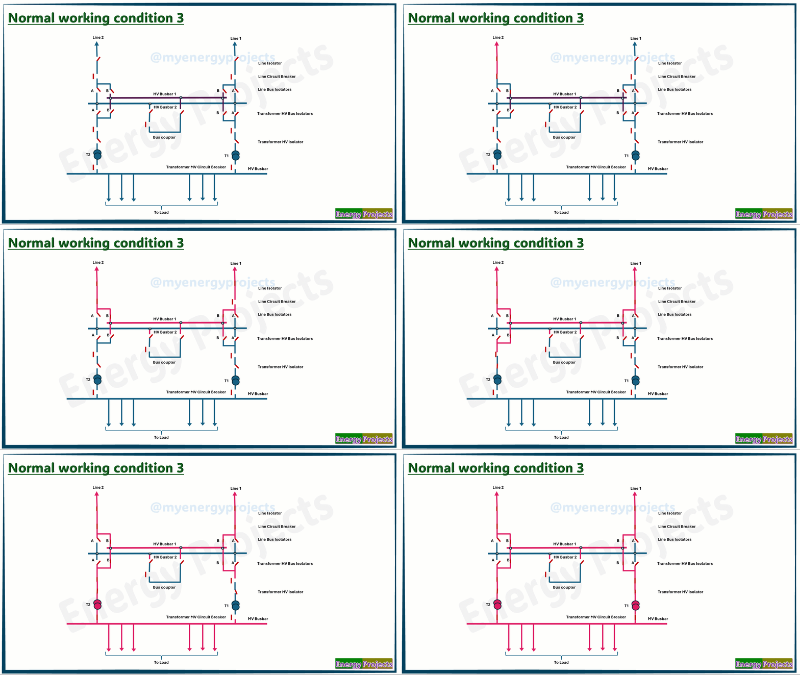
Operation 3
In this case, all bays are connected to Bus-2, as shown in the operation and power flow diagram. Line 1 and Line 2 are energized, and both Transformer 1 and Transformer 2 are also being charged.
Advantages:
Higher flexible
Less outage time
Very supportive for Protection coordination
Dis Advantages:
Very Higher cost
Very Higher space
Higher maintenance
Lower reliable if Breaker failure.


