10.How does a protection system works?
Main components in Protection system
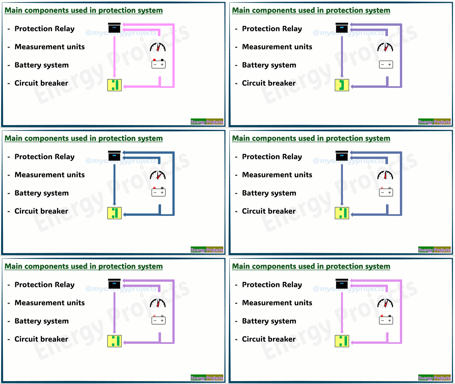
Here, we can identify the main components used in a protection system.
Protection relays are key devices that detect faults using input from measurement units, such as Current Transformers (CTs) and Potential Transformers (PTs), which are connected to the feeder circuit to monitor current and voltage levels.
A battery system plays a crucial role by powering the control circuit, which ensures the operation of circuit breakers and protection relays to isolate faulted sections of the network.
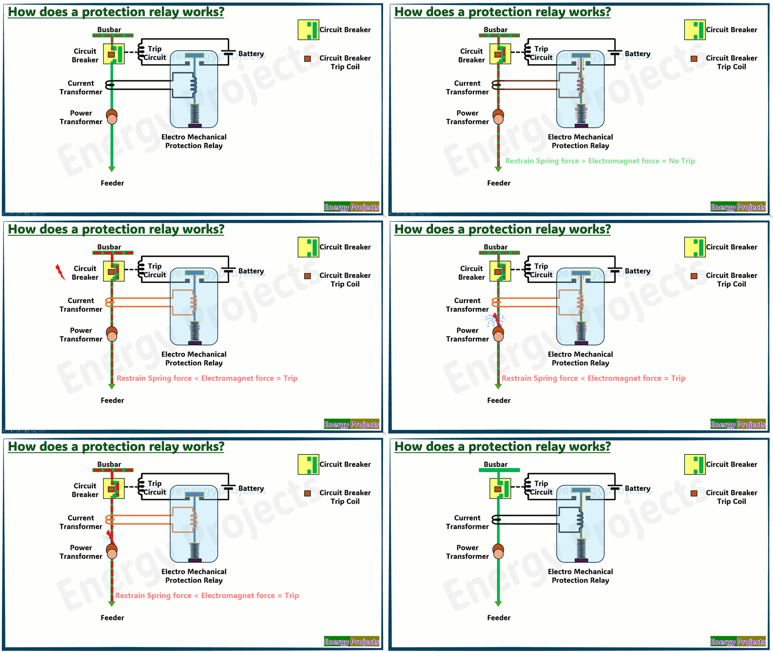
How does a protection system works as shown below diagram?
Here, we can observe how the protection system functions.
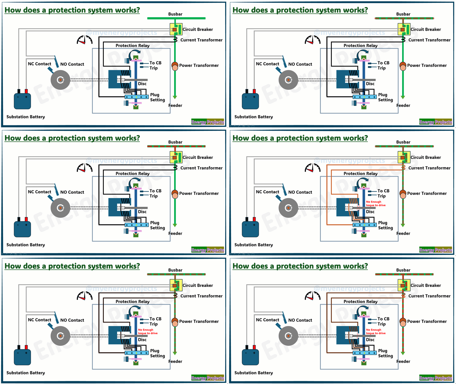
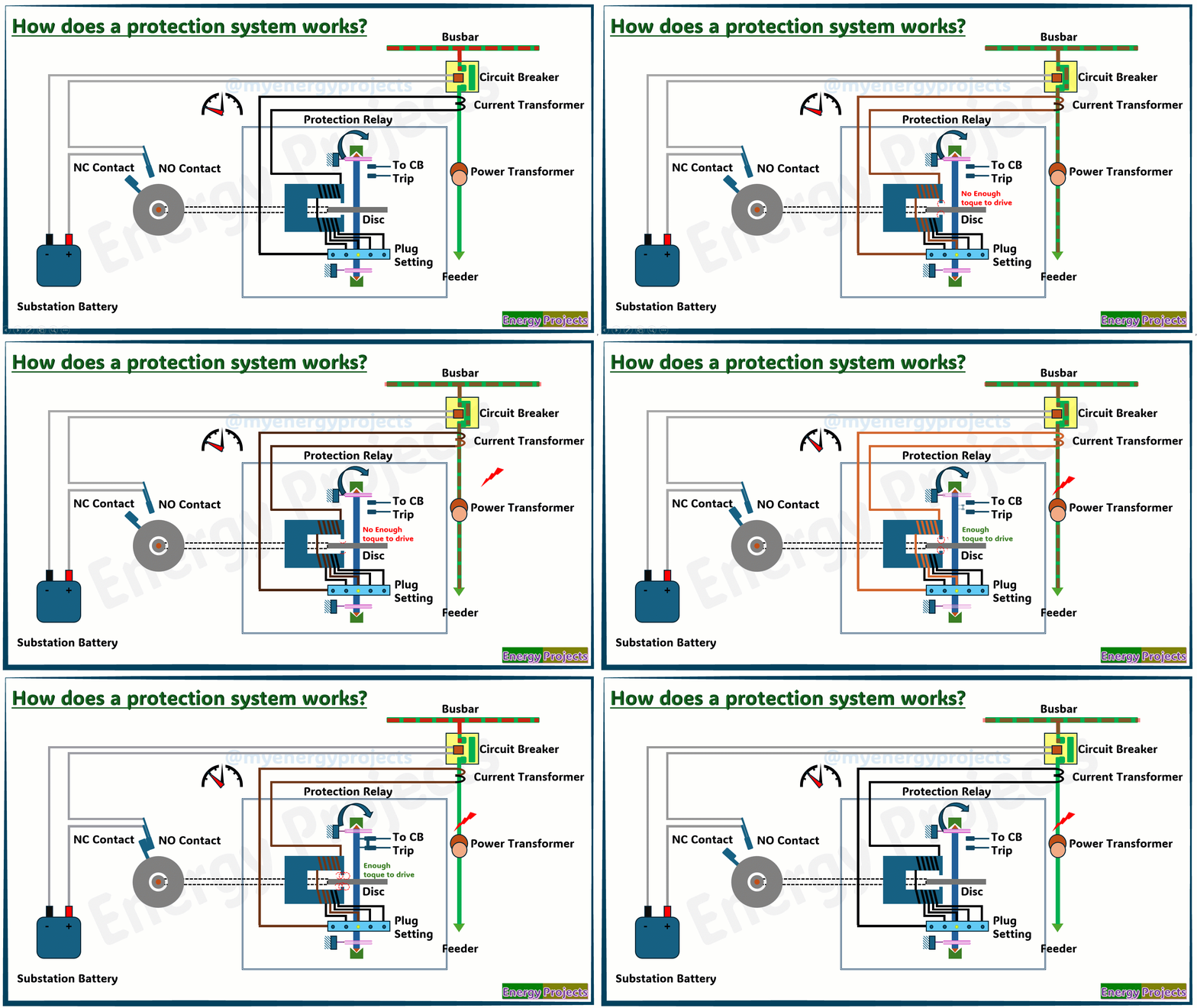
In this example, the electrical power flows from the transformer to the connected load through a circuit breaker, with a current transformer (CT) installed to monitor the current in the line. During normal operation, the current stays within acceptable limits, and although the CT continuously sends a proportional signal to the electromechanical relay, the resulting magnetic force is not enough to rotate the disc inside the relay. The torque developed is minimal and held back by a restraining spring, so the relay remains inactive. When a fault—such as a short circuit or heavy overload—occurs, the current suddenly increases. The CT detects this rise and delivers a stronger current to the relay’s operating coil. This strengthens the magnetic flux and induces eddy currents in the metallic disc, which produces a torque. Once the torque exceeds the restraining spring’s resistance, the disc starts rotating. As it turns, it eventually causes the relay contacts to shift from their normal position, closing the trip circuit. This sends a signal to open the circuit breaker, disconnecting the faulted section and protecting the system from further damage.
Normal working condition after fault clearance
You can see here that the fault is detected and controlled by the relay and circuit breaker. Once the fault is cleared, the relay returns to its default position, as the circuit breaker has already interrupted the fault current. After troubleshooting and resolving the issue, the feeder is ready to resume supplying power.
How does protection system works? ( Traditional Electromechanical Relay's)
The device operates on the principle of electromagnetic induction. A changing magnetic field induces an EMF in the metal disk. This creates circulating eddy currents that interact with the magnetic field. As a result, a torque is produced, causing the disk to rotate.
In this case, the relay is protecting the feeder, not the transformer itself. The CT and relay are positioned on the outgoing feeder side, monitoring the current delivered from the transformer to the load. Their role is to ensure that any abnormal condition on the feeder, such as an overload or short circuit, is quickly detected and isolated before it can cause damage to the transformer or downstream equipment.
The relay's sensitivity is determined by its plug setting, which sets the current level required to initiate operation. For instance, if the CT has a secondary rating of 5 A and the plug setting is set to 150%, the relay will pick up at 7.5 A (1.5 × 5 A). This is called the pickup value—the minimum current needed for the disc to begin rotating. If the actual current during a fault is, say, 15 A, then the Plug Setting Multiplier (PSM) would be 15 / 7.5 = 2. A higher PSM means the fault is more severe, so the relay will act faster due to the inverse-time characteristic higher fault currents result in shorter trip times. This coordinated response ensures reliable protection of the feeder without unnecessary tripping under normal load fluctuations.


