Mesh Busbar Configuration
Mesh Busbar Configuration:
First, we look at the very simple representation of busbar configuration.
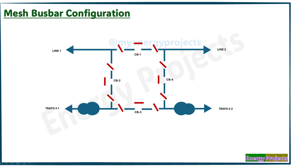
A Mesh Busbar Configuration is commonly used in high voltage substations, especially in systems that require high reliability and flexibility. It’s a hybrid between the double busbar and breaker-and-a-half schemes. In a mesh configuration, each circuit (line, transformer, etc.) is connected between two circuit breakers, and those breakers form a “mesh” of interconnected elements.
You can see the Bays are used to explain the working principle.
Line 1
Line 2
Transformer 1
Transformer 2
Normal Operation
All disconnectors will be closed, and we will charge Line 1 and Line 2. Once both lines are charged, we can close Circuit Breaker 2 to energize Transformer 1. Then, we close Circuit Breaker 4 to energize Transformer 2. At this point, Line 1 and Transformer 1, Line 2 and Transformer 2, are operating independently.
After successful operation, we can close the remaining breakers CB1 and CB3 to form a common circuit as shown.
Case 1
In this case, a fault occurs in the highlighted zone. Circuit Breakers CB1 and CB2 will trip, and a trip command will be sent to the remote Line 1 substation to isolate it from the grid. However, Line 2 continues to supply power to Transformers 1 and 2 through Circuit Breakers 3 and 4.
Case 2
A fault occurs in the highlighted zone. Circuit Breakers CB1 and CB4 will trip, and a trip command will be sent to the remote Line 2 substation to isolate it. Line 2 continues to feed power to Transformers 1 and 2 through Circuit Breakers 2 and 3.
Case 3
A fault in the highlighted zone causes Circuit Breakers CB3 and CB4 to trip. Lines 1 and 2 remain operational, supplying power to Transformer 1 via Circuit Breakers 1 and 2.
Case 4
A fault in the highlighted zone causes Circuit Breakers CB2 and CB3 to trip. Lines 1 and 2 remain operational, supplying power to Transformer 2 through Circuit Breakers 1 and 4.
Case 5
A fault in the highlighted zone trips CB2 and CB3. Lines 1 and 2 continue feeding Transformer 2 through CB1 and CB4. When another fault occurs in the highlighted zone, CB1 also trips, and a remote trip is sent to Line 1. Line 2 remains operational, supplying power through CB4.
Case 6
A fault in the highlighted zone trips CB3 and CB4. Lines 1 and 2 feed Transformer 1 via CB1 and CB2. A subsequent fault causes CB1 and CB2 to trip, and Line 1 is isolated via a remote command. Line 2 remains connected, but all breakers feeding transformers have tripped, so no power is delivered.
Case 7
A fault causes CB3 and CB4 to trip. Lines 1 and 2 feed Transformer 1 through CB1 and CB2. A new fault causes CB1 to trip and a remote trip to Line 2 is initiated. Line 1 and Transformer 1 continue working via CB2.
Case 8
A fault trips CB2 and CB3. Lines 1 and 2 feed Transformer 2 via CB1 and CB4. A new fault causes CB1 and CB4 to trip. A remote trip command is also sent to Line 2. Line 1 remains operational, but no transformers receive power as all breakers have tripped.
Case 9
A fault causes CB2 and CB3 to trip. Lines 1 and 2 feed Transformer 2 via CB1 and CB4. A new fault then causes CB4 to trip, resulting in all breakers (CB2, CB3, and CB4) being tripped. No power is supplied to the transformers.
Case 10
A fault causes CB1 and CB2 to trip, with a trip command sent to Line 1's remote substation. A subsequent fault causes CB4 to trip and Line 2 to be isolated. The entire substation is now isolated from the grid.
Advantages:
Highly reliable
Highly flexible
Minimal outage time
Supports effective coordination
Dis Advantages:
Complex design
High cost
Requires more space
Demands intensive maintenance
Troubleshooting is critical